3. Hardware Assembly
To assemble our system, we will connect our light sensor to the ESP8266 board. This involves connecting ground and power, and then the two signals needed for the I2C bus. The exact details depend on which ESP8266 board you are using (different boards have different pinouts).
Cautions
First, a few important cautions to consider when working with electronic hardware.
Avoid Static Electricity
Static electricity (e.g. that shock you sometimes get when touching a doorknob) can damage electronic components. When working with the breakout boards, you should take precautions to avoid static electricity. Some simple precautions:
- If possible, avoid carpeted floors, rubber-soled shoes, and wool clothing.
- Most computer boards and chips come in anti-static packages. Keep them in the packaging until you need them.
- Touch some grounded metal (e.g. your computer’s chassis, if it is metal) before touching any electronic components.
- Ideally, use a grounded anti-static wrist strap and mat when working with your components.
Plenty of resources about anti-static procedures are available online (e.g. [1], [2]).
Avoid Short-circuits
In digital electronics, electrical current flows from a positive voltage supply (usually indicated by a red terminal), through circuitry, and to the electrical ground (usually indicated by a black terminal). The positive power voltage is typically 5 volts or 3.3 volts. You should never allow the power lines to be connected to the ground line, without the proper electrical components in between. Ohm’s law [3] states that current flowing is equal to the voltage divided by the electrical resistance. If this resistance is zero (e.g. a direct connection), then an infinite current can flow. This is known as a short circuit. Causing one will not only destroy your electrical components, but may also damage the USB port on your computer.
OK, with that we are ready to start hooking up the hardware.
Breadboards
For easy, solderless connections that can be changed, we will use a breadboard. The picture below shows an example breadboard and the electrical connections that exist between the holes:
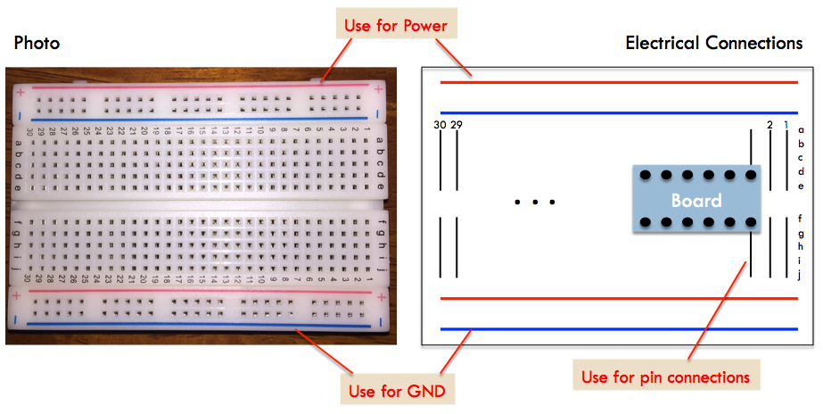
If you were to peel the backing off the breadboard, you would see metal connections matching the lines shown in the right side of the picture. These connect individual holes in a way that can be used to facilitate connections between pins on the boards by inserting jumper wires. There are four horizontal connections running the length of the breadboard that are intended for power connections. Between the top and bottom power connections, there are two rows vertical connections, with 30 columns (at least on our half-size board).
Seating and Soldering the Breakout Boards
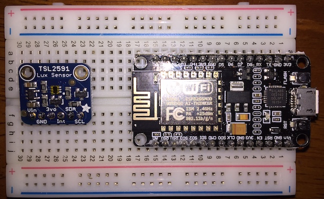
The ESP8266 and TSL2591 Breakout boards are inserted with their two rows of pins parallel to the power connections and perpendicular to the smaller columns. This allows the holes directly above and below the pins to be used for connections.
If you hold the board with the blue Ground row along the bottom, I recommend seating the ESP8266 board on the right side. The miniUSB connector should be along the right edge of the board, for easy connectivity. The TSL2591 board is then seated to the left of the ESP8266 board. The picture below shows the two boards once they have been seated:
Board connections
The Adafruit Feather HUZZAH and NodeMCU boards have different pinouts. Please follow the instructions below for your board. Note that you should do all this wiring with your board unpowered (no battery and no connection to your laptop via USB).
The wiring tables below make power connections through the horizontal power buses on the breadboards. This makes it easy to add more circuitry to the board later. If you do not plan to do so, you can wire the power pins of the ESP8266 and sensor boards directly to each other, saving a few connections. Of course, be sure to wire 3V to 3V and GND to GND.
Adafruit Feather HUZZAH ESP8266
Here are the connections to make if you have the Adafruit ESP8266 board:
| Connection Number | Signal Name | Location of Source | Location of Destination |
|---|---|---|---|
| A1 | GND | ESP8266 board pin #4
from right on top row
|
Bottom row of
breadboard
|
| A2 | GND | Bottom row of
breadboard
|
TSL2591 board
pin #2 from left
|
| A3 | 3V | ESP8266 board pin #2
from right on top row
|
Top row
of breadboard
|
| A4 | Vin | Top row of
breadboard
|
TSL2591 board
pin #1 from left
|
| A5 | SDA (GPIO #4) | ESP8266 board pin #1
from left on bottom row
|
TSL2591 board
pin #5 from left
|
| A6 | SCL (GPIO #5) | ESP8266 board pin #2
from left on bottom row
|
TSL2591 board
pin #6 from left
|
Here is a logical wiring diagram:
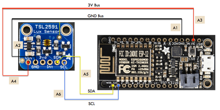
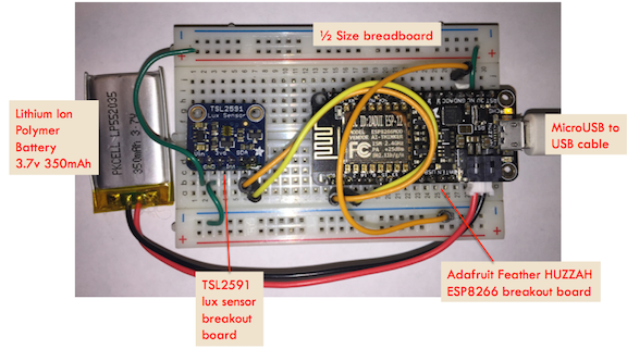
And, finally, here is a photograph of the completed system using the Adafruit Feather Huzzah board:
Now, please skip down below to the Verifying Connections section.
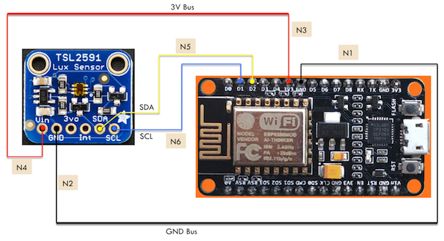
NodeMCU
Here are the connections to make if you have the NodeMCU ESP8266 board:
| Connection Number | Signal Name | Location of Source | Location of Destination |
|---|---|---|---|
| N1 | GND | ESP8266 board pin #7
from left on top row
|
Bottom row of
breadboard
|
| N2 | GND | Bottom row of
breadboard
|
TSL2591 board
pin #2 from left
|
| N3 | 3V3 | ESP8266 board pin #6
from left on top row
|
Top row of
breadboard
|
| N4 | Vin | Top row of
breadboard
|
TSL2591 board
pin #1 from left
|
| N5 | SDA (D2) | ESP8266 board pin #3
from left on top row
|
TSL2591 board
pin #5 from left
|
| N6 | SCL (D1) | ESP8266 board pin #2
from left on top row
|
TSL2591 board
pin #6 from left
|
Here is a logical wiring diagram:
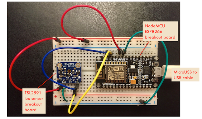
And, finally, here is a photograph of the completed system using the NodeMCU board:
Verifying Connections
Now that the system has been wired up, we can verify the connections. You might start by visually inspecting the connections to make sure they match the wiring diagram. Pay special attention to the 3V and ground connections to avoid short circuits. If you are unsure, set your multitester to resistance mode and check the resistance between GND and 3V. It should be a high value.
Now, you can use the microUSB to USB cable and connect your system to your laptop. You should see an LED light up (at least briefly) on the board. You can test the power connection by setting your multitester to voltage mode, placing the black lead on a GND pin, and the red lead on a 3V pin. You should see a voltage around 3 volts.
Now, we are ready to install the firmware and software!
| [1] | http://www.howtogeek.com/169994/how-to-protect-your-pcs-hardware-from-static-electricity-when-working-on-it/ |
| [2] | http://www.wikihow.com/Avoid-(Static)-Electric-Shock |
| [3] | https://en.wikipedia.org/wiki/Ohm’s_law |
| [4] | https://learn.adafruit.com/adafruit-feather-huzzah-esp8266/assembly |
| [5] | https://learn.adafruit.com/adafruit-tsl2591/wiring-and-test?view=all#assembly |